IMPR-RAD-01
The first field-tested RAD-01: a complete mesh node that keeps a team on one ATAK picture, with its signals on two pin headers.
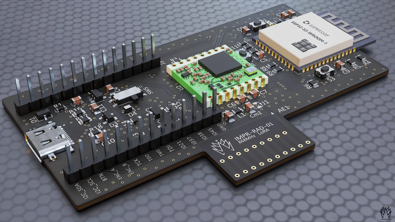
The original field-tested node
Rev1 runs the same mesh firmware and ATAK integration as Rev2: an ESP32-S3 core, an SX1276 LoRa radio and a 600 mA rail, with power, UART, I²C, display, encoder and JTAG lines on two 14-pin headers.
Designed and built in-house: hardware, mesh firmware, ATAK integration and telemetry.
Radio and core on one board, signals on two headers
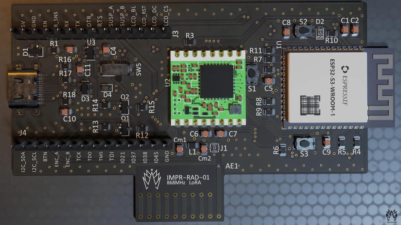
- 01 An ESP32-S3 runs the mesh firmware across LoRa, Bluetooth LE, ESP-NOW and Wi-Fi.
- 02 An SX1276 LoRa radio module at 868 MHz, with an on-board antenna and RF connector.
- 03 A 600 mA 3.3 V rail, fed from USB-C.
- 04 Two 14-pin headers bring out power, UART, I²C, display, encoder and JTAG lines.
Specifications
Radio & power
- Transceiver
- SX1276 LoRa module
- Band
- 868 MHz
- Antenna
- On-board, with RF connector
- 3.3 V rail
- 600 mA
- Power input
- USB-C
Core
- MCU
- ESP32-S3 · 8 MB flash · 8 MB PSRAM
- Links
- LoRa · BLE · ESP-NOW · Wi-Fi
- Debug
- USB · JTAG
- Buttons
- Reset · boot · radio reset
Mechanics & expansion
- Outline
- ≈ 82 × 50 mm
- Stack-up
- 4-layer PCB
- Assembly
- Single-sided
- Expansion
- 2 × 14-pin headers · 2.54 mm
Two revisions. Both field tested.
Rev1 is a complete, field-tested node. Rev2 keeps the same core and adds room to grow: expansion ports, a larger power budget for the modules on them, and a newer LoRa radio chosen for its lifecycle.
Headers on Rev1. Ports on Rev2.
Rev1 brings its signals out on two 14-pin headers for wiring in peripherals. Rev2 replaces them with three stacking expansion ports.
Two 14-pin headers
Power, UART, I²C, display lines, encoder inputs, JTAG and spare GPIO on 2.54 mm headers.
Request the PinoutThree expansion ports
One port on top for display modules such as IMPR-DISP-01, two underneath for extension modules.
View Rev2Your custom module
Need a sensor, power or I/O module for your program? We design custom modules to the same connectors, so they stack on a fielded node.
Discuss a Custom ModuleATAK over the mesh.
Works with ATAK-CIV 5.5+This is how we run RAD-01: each operator’s phone pairs with a node, and the team keeps working in ATAK as usual. The mesh carries the shared picture where there is no tower, server or internet.
Phone to node over Bluetooth LE or Wi-Fi; node to node over LoRa.
- Positions
- Markers
- Drawings
- Routes
- Chat
- Images
- Voice
- Video
-
One picture for the whole team
Positions, markers, drawings and routes reach every node on the mesh, so everyone works from the same map.
-
Chat built for gaps
Messages for someone out of reach wait in the mesh and go through when they come back in range.
-
Several phones per node
Phones connect over Bluetooth LE or Wi-Fi, so one node can serve several operators.
-
Nothing new to learn
The mesh works underneath ATAK. Operators keep the map, chat and markers they already use.
Images, voice and video need more bandwidth than LoRa gives. They move to the HaLow link of IMPR-VOX, now in field test.
Discuss a Mesh DeploymentA software-defined radio with 2×2 MIMO.
A modular Linux and FPGA radio core that will carry the same TAK traffic over Wi-Fi, Bluetooth LE, LoRa and HaLow, with a replaceable 2×2 SDR card for a higher-throughput mobile mesh. It runs our existing VOX and DISP-01 modules.
Ask About PRIMARCH- SDR card
- 2×2 coherent: two transmit and receive chains
- Tuning range
- 325 MHz – 3.8 GHz
- Bands
- 868/915 MHz, L band and part of S band
- Channel width
- Up to 20 MHz
- MIMO roadmap
- Diversity (STBC) first, then spatial multiplexing
- Upgrades
- Swappable radio cards for other bands
In design: performance figures will be published only once measured.
Need a mesh node like this for your program?
Ask about RAD-01 and its modules, or have the team that built them design yours. Mutual NDA first; a full proposal with budget and timeline before any work starts.